Matt Luongo's Portfolio
Matt Luongo
Natick, MA Based Thinker, Doer, and Lover of Engineering.

About me
My name is Matt. I graduated from Northeastern University with a master's degree in mechanical engineering. I like designing things in CAD before getting hands-on with prototyping and testing my designs.Aside from mechanical design, I really like cooking and collecting music.
Samples and Projects
Browse samples from my full-time work experiences, co-ops, and coursework at Northeastern University.
Skills
CAD: SolidWorks, Onshape, Inventor
Simulation: Ansys, SolidWorks FEA
Software: MATLAB, Arduino, Python, ros, Linux
Other: Excel, PDM, Jira, Vizio
Quick Links
This site is a work in progress. Thanks for visiting my site!
Matt Luongo's Portfolio
About Me
Bio
My name is Matt. I'm a creative problem solver with a master's degree in mechanical engineering. I enjoy creating new designs in SolidWorks, building prototypes, and iterating upon those designs. Building things has been my primary interest ever since the age of 5 when I received my first Lego set. I began to refine my goals at 14, I joined my high school's FRC robotics team. After 4 years of design and fabrication, I knew exactly how I wanted to spend my career.
Education
I received my BSME and MSME from Northeastern with their PlusOne program. As part of the program, I began taking graudate courses in 2021, which double-counted towards my undergraduate degree.Master of Science in Mechanical Engineering — Mechatronics Concentration — June 2023 — 3.83 GPA
Bachelor of Science in Mechanical Engineering — December 2022 — 3.54 GPARelevant courses: Mechatronic systems, where I designed and modeled a closed-loop PID controller for a DC motor using Simscape and Simulink's Arduino support module; Robot mechanics and control, where I learned about manipulator kinematics, Jacobians, and how to design closed-loop controllers for manipulators; Robot sensing and navigation, where I wrote and implemented GPU and IMU drivers with Python and ros; and Finite element method, where I learned the fundamentals behind FEA and how to perform analysis using APDL and handmade MATLAB scripts.
My Hobbies
I love to try new recipes in the kitchen. Cooking is dependant on scientific phenomena, like the Maillard reaction that causes browned meat to taste good, or the chemical compounds that give fruits, vegetables, herbs, and spices their distinctive tastes. I like cooking because even newer cooks, like myself, can experiment with flavors and iterate on their favorite recipes.My favorite thing to collect is music. Cassette tapes are my favorite music format, because of the click-clack and overall feel of loading a tape into a deck. I like vinyl records as well, especially because of the art.For a tired engineer like myself, cats are the best kind of pet. Bean (not pictured) has been with my girlfriend's family for around 10 years, and has lived with us since we moved to Jamaica Plain in 2022. Slug and Steve (pictured below) are new additions to the family, and were adopted in October 2023 after we moved to Natick.I am also an avid video gamer. I don't always have time to play nowadays, but I enjoy single-player games and rogue-likes/-lites when I have time.
Gallery


This site is a work in progress. Thanks for visiting my site!
Matt Luongo's Portfolio
Competencies
Design
Between my work experience and co-ops, I have design experience in the following areas:
SolidWorks, Onshape, Inventor
Technical drawings
DFM/DFA
P&IDs
Sheet metal
Small weldments
GD&T
Design against a set of requirements
I have used CAD programs since high school when I started out with Inventor, so I feel confident attacking different kinds of problems in SolidWorks. The drawing review process at Desktop Metal was very personal, so I learned about drawing standards and review methods from the most experienced engineers.When making a design, I am constantly thinking about how the machinist will fabricate the part, what processes and tools they will use, and how it will be assembled after being finished. I designed a couple sheet metal parts and a weldment at Desktop Metal, and know the basics of implementing a cutlist on a drawing.For GD&T: I learned about using true-position on drawings and virtual condition to see if tolerances are large enough. I also have familiarity with concentricity, parallelism, and surface envelope tolerances. I have a little exposure with tolerance loops and stackups (not strictly GD&T) but I need a little experience implementing them before I am confident.
Fabrication
I have used the following manufacturing methods at my co-ops or on my FRC team in high school
3D Printing (Prusa, Stratasys, Objet, Bambu, etc.)
Manual milling
Manual turning
CNC milling (2.5 axis)
Brakes, notchers, taps, saws, etc.
Software
I have school experience in all of the following software:
Microsoft products (Excel, Powerpoint, Vizio)
MATLAB (incl. analysis, data aquisition, FFTs, FEA scripts, Bode diagrams, etc.)
Simulink (incl. Simscape, Simulink Support Package for Arduino, transfer functions, controller design)
Python
ROS
Linux
Bash
Git
Exposure to C++
I feel very confident attacking problems in MATLAB and Simulink. As part of my curriculum, I have solved problems in topics ranging from finite element method to control theory using these programs.My exposure to Python, ROS, Linux, bash shell, and git CLI come from my robot sensing & navigation course. In this course, I learned how to implement sensor drivers using Python and ROS. I collected datasets in rosbags and performed analysis using Python and MATLAB.
Analysis
MATLAB FEA scripts
APDL
Ansys Workbench
PLM
SolidWorks PDM
Salesforce Propel
Atlassian (Jira, Confluence)
Other Skills
I consider myself a fast learner, and I enjoy adding new skills to my repertoir. I can manage my time well across multiple projects at once. The most satisfying reward for me is a job well done. I mesh well with my coworkers. While I always try to advance a project as far as I can by myself, I am comfortable asking for guidance when needed.
Topics I am Interested In/Want to Learn More About
More GD&T callouts
Large weldments
System identification
Optimal control theory
Electromechanical system design
Kalman filters and complementary filters
This site is a work in progress. Thanks for visiting my site!
Matt Luongo's Portfolio
Work Samples


Pictures of the old coupling
Flex Couplings (Desktop Metal)
The P-50 metal 3D printer relies on metal drums to supply powder to the system and to collect overflow powder. Drums are frequently purged with inert gas, which results in pressure buildup in each drum. Flexible connections ("flex couplings") act as replaceable hermetic seals that technicians would uncouple and recouple to change out drums. The flexible rubber couplings that were originally selected for use on the printer had multple issues:
Relatively low pressure rating
Couplings stretched a lot when pressurized
The coupling ID shrank as the coupling was compressed
The rubber couplings were prone to ripping
I was tasked with finding a comprehensive solution to all (or most) of the problems. Here's what I accomplished:
Collected drum pressure data for a variety of gas flow rates
Developed a set of requirements for the solution, including pressure margin, purge time, cost, and timeframe
Built a list of potential replacement products by working closely with vendors
Brainstormed creative alternatives to new couplings
Selected and evaluated the most promising solutions in a clear format
Delivered an exceptional concept design review (CDR) with a concise explanation of my process, findings, and recommended next steps
In the end, we chose to move a pneumatic butterfly valve between the flexibe coupling and the drum, which protects the coupling from high pressure. A flexible support structure would be designed to support this valve. A purchased coupling with a convoluted design and structural wire was selected to prevent the ID from constricting.
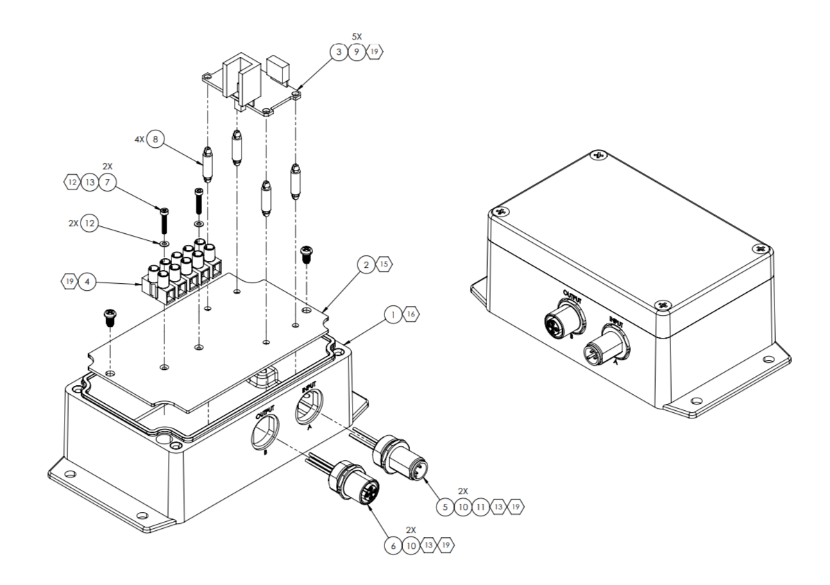
Proportional Valve Upgrade
A pneumatic valve used in the P-50 printer kept failing, so a proportional valve was selected to replace it. I was tasked with designing an enclosure for the valve controller board.I sourced an off-the-shelf enclosure and modified it to fit a circuit board. With the help of our in-house machinist, I prototyped the modified enclosure and implemented it on the test printer. In addition to releasing the drawings, I updated the printer gas panel drawing and the printer P&ID.
Facilities Plate
The P-50 printer had a bulkhead plate with ports for air, nitrogen, water, and some electrical cables. A few new bulkheads had to be added, and the old design had some opportunities for simpificaiton.I designed a simple weldment with a drip tray, grounding stud, and bulkheads grouped based on function. I released the drawings and created redlines for the upper-level drawings affected by this change.
Covaris Projects (2nd Co-op)
Alignment Verification Tools
I designed these tools for measuring the alignment of the R230 end effector to its working area. These tools measure yaw and pitch of a rectangular bracket using dial and digital indicators.
Blowout Fixture
I redesigned a critical fixture used to clean out sample plates before packaging. I also sourced the parts for a second fixture, built it, and installed it in the clean room used to manufacture consumables.
This site is a work in progress. Thanks for visiting my site!
Matt Luongo's Portfolio
School Projects
Capstone
My capstone team designed an attachment for a 3D printer that enabled targeted, in-situ annealing on semi-crystalline polymer parts. While annealing of 3D prints can be done in an oven, our solution was intended to minimally increase production time while maximizing the properties of parts in specific, failure-prone areas.
The motivations behind annealing plastics differ from metals. Annealing a material like steel tends to relieve internal stresses and make the material more flexible. Annealing semi-crystalline polymer parts causes crystallization (e.g., extension of polymer chains), which results in a stiffer and stronger material.Our heating attachment consists of the heater assembly, an Arduino-based control circut, and DC power source. We fitted it onto a Prusa i3 MK3S+. The brass block is heated with the cartridge heater, and is held very close to the part. Heat is transmitted via conduction through the small air gap, free convection, and radiation.I designed a bracket that is mounted on the Prusa's hotened. I also wrote the Arduino code for the control circuit. The script acts like an open-loop controller. It opens a relay if the heater temperature is lower than a target, and closes the relay if the temperature is too high. The control circuit is connected to the hotend fan header on the printer's control board. We modified the gcode files to pulse the fan at the beginning and end of heating phases, and the Arduino waits for these pulses before starting to control the temperature.We added heating passes to the gcode after every couple layers. The 'pass' involves the heater moving to a fixed location to anneal a weak point on a part. We designed dogbone tensile bars with an intended failure point at the middle. The intent was to compare performance of test articles with targeted annealing at the failure point against untreated articles.
In order to determine the annealing temperature, we used DSC to find the glass transition and melting temperatures of PLA. We settled on an intended surface temperature of 100°C. We determined how long to hold the part at temperature by modeling the part as a semi-infinite surface (e.g. temperature is a function of Z only) and calculating the temperature as a function of time in MATLAB. We used a hold time of about 5 minutes and annealed 2 layers at a time.We spent a lot of time brainstorming, and some of our other concepts can be seen in the report linked below. In the end, we saw a 12% increase in ultimate tensile strength for the annealed parts. I also delivered an exceptional speech during our pitch on capstone day. A significant downside of our product is that it adds a significant amount of time to printing.
If I could redo this project, I would start by changing the heating element. A brass block heats well through conduction, but we had to transmit energy through an air gap into the part. I think a convection-based concept (e.g., hot air) or something like a burning laser would be a far more effective energy delivery method. I would also try to implement a closed-loop controller with an IR thermometer that could directly measure the surface temperature of the part. Since we relied on an open-loop controller with a thermocouple embedded in the heating block, we were working blind for pretty much the whole project. Overall, I still consider this capstone project a relative success in achieving our goal of making a targeted, in-situ annealing attachment for a 3D printer.
GPS and IMU Sensor Fusion Project — Robot Sensing & Navigation
I wrote drivers for a GPS puck and an IMU in Python. I implemented these drivers in real-time using ROS, and collected data while driving around the streets of Boston.
After collecting data in rosbags, I graphed and analyzed the data in MATLAB. After calibrating the magnetometer data, I generated plots of yaw vs. time derived from the magnetometer, gyroscope, and complementary filtered data.
Next, I integration to obtain forward displacement. Integrating the raw acceleration data resulted in a number of biases that I had to account for.Combining yaw and displacement yielded enough information to plot the motion of the car. I compared the 'true' GPS data against the motion derived from the complementary filter and the gyroscope. Because of how I implemented my complimentary filter, the plot of motion I derived looks like nonsense; however, the plot of motion derived from the pure gyroscope data resembles the GPS data.
I consider this project a half-success, since it proves that IMU data can be used to interpret vehicle location in the event a GPS loses connection. In most real-life cases, magnetometer and gyro data will be fused to obtain a more accurate measurement. I hope to learn more about complementary filtering in a future work opportunity.
APDL Analysis Project —
Finite Element Method
I analyzed a honeycomb frame under different types of loading using Ansys. I learned how to apply different member properties and element types using APDL. I applied boundary conditions and loads in 3 schemes: Normal in X, normal in Y, and shear in XY. Finally, I calculated the effective stiffness for each kind of loading.For an asymmetrical honeycomb pattern, the properties of the frame are anisotropic. See the report for more details and the full code.
Motor Controller Project —
Mechatronics
I designed a PID controller for a DC motor using Simulink Support Package for Arduino. First, I constructed a model of the motor in Simscape. This required collecting data from the motor and using differential equations to derive characteristics like Kt and Kb.Next, I used Simulink to build a control loop for the motor. The loop reads a reference input from a potentiometer on a breadboard, converts it to a PWM signal, and sends it to the motor. The motor's built-in encoder closes the loop by supplying feedback.
Finally, I characterized the controller's performance by collecting data and comparing it to the simscape model. My controller demonstrates a settling time of around 20 seconds with around 30% offshoot. Since the motor was relatively low quality, small inputs did not overcome the friction inside the motor, so the integral term was critical for achieving a small steady-state error.
Swerve Module Project —
FRC (Walpole High School)
I designed, machined, and assembled this 'swerve module.' The wheel and housing can rotate independantly of each other. Combining 4 of these on a drivetrain allows a robot to move in any direction.It's mounted to a piece of U-channel for display purposes only (it's what I had lying around). To implement these on a real drivetrain, each module usually gets one motor for driving the wheel and one for orienting the housing.
This site is a work in progress. Thanks for visiting my site!
Matt Luongo's Portfolio
References
Please feel free to contact any of my co-workers at Desktop Metal to learn more about how I work. The co-workers with whom I interacted with the most are listed here (with permission).
| Name | Title | Relationship | Phone | |
|---|---|---|---|---|
| Thomas Nilsen | Director of Mechanical Engineering | Supervisor | (508) 768-5149 | [email protected] |
| Kurt Joudrey | Principle Mechanical Engineer | Supervisor | (617) 834-6841 | [email protected] |
| Jim Faso | R&D Hardware engineer | Supervisor/Co-worker | (603) 521-2185 | [email protected] |